

| Back to
Relays |
|
| Automotive Relay Diagram | |
Relays are switches controlled by electrical power, like another switch, computer or control module. The purpose of a relay is to automate this power to switch electrical circuits on and off at particular times. The real benefit behind a relay is more than automation. They also provide the ability to switch multiple circuits, including different voltage types, within the same relay at the same time.
12V DC relay switches are the best solution for full voltage applications, as they allow a low current flow circuit to control a high current flow circuit, like a vehicle's horn, headlights, auxiliary lamps, fan motors, blower motors and countless pieces of equipment existing on vehicles today.
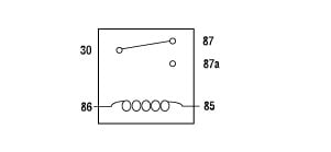 |
Looking Inside a Relay If we were to open a relay, you would see an electromagnet coil, the contacts, and a spring. The spring holds the contact in position until a current gets passed through the coil. The coil then generates the magnetic field which moves the contact on and off. |
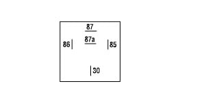 |
Numbers of a Relay Looking at the diagram, we see the pinout of a typical 12V relay. Note that each pin is numbered. 85 and 86 are the coil pins while 30, 87, and 87a are the contact pins. 87 and 87a are the two contacts to which 30 will connect. If the coil is not activated, 30 will always be connected to 87a. You can think of this as the switch in OFF. When current is applied to the coil, 30 is then connected to pin 87. You can wire relays to be either open or closed, depending on how you need your accessory to operate. If you want a normally closed relay, you will want to wire to 87a. If you want a normally open relay, you will wire to 87. Although most relays are labeled at the bottom, you can always find the 30 pin set perpendicular to pins 87 and 87a for easy identification to the power source. |
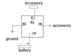 |
Output for a Relay Realizing that 85 and 86 are the coil pins, these pins will be transferring the current through the coil. 85 will be used to ground your relay, while 86 will be connected to the switchable power. 87 and 87a will be connected to your controlled accessories that you wish to turn on and off with your relay. 30 will then be the pin connected to your battery power. |